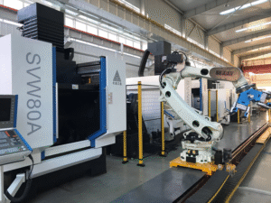
Accuracy recovery of five-axis linkage machining centers
After a period of use, high-precision five-axis machining centers experience a decline in mechanical accuracy due to factors such as cutting impacts, wear and tear on moving parts, and foundation settlement. How to maintain high machine tool precision and ensure that the quality of precision parts meets standards? Dalian Sanlei Technology, drawing on over ten years of practical experience in five-axis precision machining, offers a comprehensive solution to these problems.
I. Factors Affecting Machining Center Accuracy and Daily Control
1. Temperature: Many factories without precision machining experience perform precision machining immediately after the machine starts working. However, the accuracy of the first batch of samples often fails to meet standards, leading them to attribute the instability to equipment quality issues. However, they are unaware that ambient temperature and the machine tool’s thermal balance have a significant impact on machining accuracy. Even high-precision machine tools can only achieve stable machining accuracy under stable temperature and thermal balance conditions. The best way to solve this problem, besides ensuring the machine tool operates in a constant temperature environment, is to thoroughly preheat the machine tool before each machining session. Sanlei Technology’s built-in warm-up program scientifically plans the multi-axis linkage of the machine tool, allowing it to repeatedly perform preheating actions.
2. Machine Tool Level: The level of a CNC machine tool is also a crucial indicator affecting its accuracy. Therefore, the machine tool should be regularly checked and leveled. Most machine tools today are cast iron, and leveling is a means to prevent deformation.
3. Ambient Air and Humidity: The dust concentration in the air must not exceed 10 mg/m³, and the air must not contain acids, salts, or corrosive gases. The machine tool must not be used in environments with flammable gases or potential explosions. When the maximum temperature is 40℃, the relative humidity should not exceed 50%; when the temperature is 20℃, the humidity should be 40-70%. Failure to meet these requirements will not only affect the machining accuracy of the machine tool but also its service life.
II. User-Level Accuracy Recovery of Five-Axis Machining Centers
User-level accuracy recovery of five-axis machining centers can be divided into five-axis linkage accuracy recovery and positional accuracy recovery. Five-axis linkage accuracy includes zero-point recovery for each of the five axes and five-axis ball bearing accuracy. Positional accuracy is determined using a laser interferometer. To achieve optimal machining accuracy, the zero-point coordinate offset of each axis should be calibrated every 3 months, the five-axis calibration sphere every 6 months, and the laser interferometer every 12 months (geometric accuracy should be calibrated every two quarters, which is acceptable in a temperature-controlled workshop barring accidents). Restoring the accuracy of five-axis linkage and position is interconnected in many adjustments; often, changing a single parameter will alter the entire machining center’s existing accuracy.
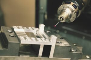
Zero-point calibration: To calibrate the XY zero-point coordinate offset, use a gauge to find the concentric position of the rotary table and spindle, and record the actual reference point of the machine tool at the current concentric position. Add the error between the calculated and correct values to the system folder. This is located in Axes-ParameterSets-Required Axis-CfgReferencing-refPosition. For the Z-axis, use a standard tool and gauge block, then subtract the standard tool and gauge block values from the total length to obtain the actual Z-axis reference point value. If it is not a calculated value, add the error to the system file.
Calibrate the Five-Axis Coordinate System
1. Before calibrating the five-axis sphere, the zero point must be calibrated.
2. Clamp the calibration sphere in the spindle tool holder and correct the runout. Input the tool length and sphere radius into the tool table. For the rotary axis linkage calibration, first move the axis to any position left or right of the X-axis center in the Y-direction, or to any position left or right of the Y-axis center in the X-direction. Move the axis along the axis direction to find the highest point. Then execute the M128 command to rotate the C-axis and observe the errors in the table for each axis direction. Add the error values to the system folder Channels-Kinemation-CfgkinSimpleTrans-K21 Axis Files-val.
3. For the flip axis calibration, move the axis to any position left or right of the X-axis center in the Y-direction. The distance between the Z-axis sphere tip and the worktable should not be less than 200mm to avoid collisions. After finding the highest point, execute the M128 command to flip the A-axis by ±90 degrees. Observe the error values in the table and add them to the system file. Compare the calibrations with the sphere tip below, in front of, and below the sphere. The B-axis is calibrated similarly.
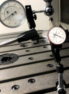
Correcting Geometric Accuracy
1. Use a straightedge to check the dial indicator on the worktable. If there is an error, resurface and adjust the relevant axis shims.
2. Use a square to calculate the perpendicularity of the clamp. If there is an error, resurface and adjust the relevant shims, ensuring parallelism is not compromised.
3. Use a gauge bar clamped on the spindle to check the dial indicator. If there is an error, check the perpendicularity relationship and resurface the spindle end face and the Z-axis slider adjustment shims.
Correcting Positional Accuracy
Measure each axis with a laser interferometer and then input the parameters into the PLC parameter file.
The above is the adjustment scheme for restoring the accuracy of a five-axis linkage machining center. Our company provides professional calibration services for customers who purchase our equipment. Please contact us if needed.